PC Interfacing
Via the Ethernet
Copyright© 2001 Eddy Insam - email:
edinsam@eix.co.uk
Published In Electronics
World: May/June 2001
Abstract box
Connecting external devices to your PC via your local network
is not as difficult as it seems. Eddy Insam explains how it all works, what
you need to know and describes a development device that can get you going in
no time at all.
 You
are browsing the Internet looking at you car's
own web page. The screen is full of messages and indicators telling you all
about your car, but an orange flag tells you there is something that requires
your attention. You look at the various gauges: clutch, brake fluid, they seem
OK. Oil looks a bit low though, so you place a tick under one of the oil brands
in the "garage remainder" memo pad.
You
are browsing the Internet looking at you car's
own web page. The screen is full of messages and indicators telling you all
about your car, but an orange flag tells you there is something that requires
your attention. You look at the various gauges: clutch, brake fluid, they seem
OK. Oil looks a bit low though, so you place a tick under one of the oil brands
in the "garage remainder" memo pad.
You wonder how people did this in the past; did people actually
open the bonnets and look inside their own cars? Then the door bell rings, the
washing machine repairman is at your doorstep.. "Your dishwasher just e-mailed
us to say its drive belt is just about to go."
Whether you think the concept of networking your possessions
is a good thing or not, it may be of some use knowing how it all works. In any
case, this article is for you because it will at least put you on the first
step of the "I am not afraid of the technology" ladder.
On the other hand, you may be thinking of network-enabling
your own product or application, and may have been put off by the apparent complexities
involved. This article will give you an insight into the expertise and effort
involved. What's more, the preprogrammed chip available from the author (described
in next month's article) will give you a head start on the prototyping stage.
As a consultant, I am sometimes asked about the Internet and
its potential extended uses. Boring as the subject may be, the conversation
sometimes ends in opinionated discussions about the need for Internet fridges
and microwaves that e-mail you when the noodles are ready.
Nevertheless, there are some interesting possibilities for
considering the use of a local area network as a serious interface between a
PC and external I/O devices. For one, it means the two can be as remote from
each other as need be (anywhere in the world in theory). You can also share
a device among several users, say a rooftop webcam or weather monitoring station
accessed by all users in a building or school (or even from home).
There are benefits at the practical level too. Remote data
logging and controlling equipment becomes much easier when it can all be done
using standard and well-tested networking components, cabling and connectors.
New network models such as RTPS (Real Time Publish Subscribe)
are also making Ethernet more suitable for real time systems, data logging and
control. Interesting possibilities arise too when interfacing
to other proprietary networks such as Home Automation, X10, CEBus or LON. But
then, it can all sound very complicated: the protocols, the stacks, and so little
information published - but is it? The answer is not really, and certainly not
out of reach.
 Embedding
is the word
Embedding
is the word
Internet-enabled hardware products are slowly becoming commonplace.
From vending machines dialling up to report their stock, to pinball machines
publishing their high scores on the Internet for all to see.
Internet appliances (the term used for browsers that do not
use a computer) are predicted to overtake PCs for Internet use within the next
four years. A new addressing scheme for the Internet (version 6) allows for
a staggering 2^96 times the number of addresses currently available (the address
field is 128 bits). Each nut and bolt in your washing machine will be able to
have its own unique Internet address.
Many modern products are driven by internal microprocessors.
These small devices are quite powerful, but one generally omitted fact is that
in order to implement the functionality required for internet and network access,
a lot of program code space is required. Gone are the days of simple ASCII dial-up
interfaces, simple ZMODEM or Kermit protocols. Nowadays your processor has to
deal with PPP, ARP,IP, ICMP, TCP and a host of others. More on this later.
Of PCs and interfaces
PCs are well known for their lack of suitable interfaces into
the real world. PCs were not originally designed with many facilities for driving
external equipment or to act as data gathering stations. Many alternatives using
the parallel and serial port have been on offer, but this approach is becoming
less practical nowadays, especially with NT and Windows 2000 where special low
level software system drivers are required.
Worse still, parallel and serial ports are now called ‘legacy’
devices, which is computer jargon for obsolete. The newest machines from the
shops just do not have these ports any more. These are all being replaced by
USB. USB devices may eventually be accepted as the standard method for general
purpose direct, local interfacing to a PC.
The advantage of using a network, as opposed to a direct connection
is distance. Most PCs will have a local network connection. Low cost Ethernet
cards are readily available and easy to install, even in older and non-PC machines.
From this point of view the use of Ethernet for I./O external access is an attractive,
cheap alternative. Furthermore, different brand, newer and older machines with
different operating systems can access the devices. Macs, Linux, Unix and portable
handheld devices can all be used. Fig 1.
Not forgetting the software at The PC end
If you develop a piece of network hardware, you will need
to think about how to drive it from the PC. You may not need to write any software
at the PC end at all. Your device could for example emulate a web page, and
be accessed as if it were a normal Internet page. If you need more dedicated
control, standard API libraries are available for network communications. The
one in Windows is called Winsock, a family of API calls contained in a DLL file.
There is also higher level support in the form of ready made OCX components,
add-ons for Visual Basic and C. The listing at the end of the article
shows a simple 'C' demonstration program showing how Winsock calls can be used
to send and receive data from a remote on the network.
How do they do that?
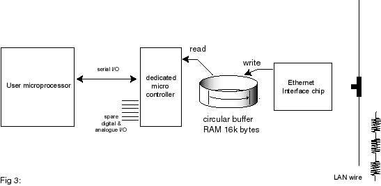
Fig 3 shows a block diagram
of the business end of a simple Ethernet embedded device. It consists of a small
dedicated microprocessor connected to a custom Ethernet interface chip, which
is in turn connected to the local area network via suitable electrical isolation
transformers. The Ethernet interface chip acts like a sophisticated serial-to-parallel
converter. Its job is to read serial packets of data from the wire, check their
header bytes with an internal address, perform checksum calculations, and push
the block into a user accessible First In First Out data buffer. The FIFO queues
the data blocks for processing by the application. The job of the microprocessor
is to retrieve the blocks, and according to the information within, perform
a few more data calculations and checksums, then pass the 'clean' data on to
another device or system. The micro must be quick enough to retrieve frames
from the FIFO buffer before it overruns, otherwise packets may be lost.
 During
transmission, the opposite takes effect. The microprocessor places data blocks
in a buffer, the Ethernet chip then adds any required headers and checksums,
perform the parallel-to-serial conversion and then push the serial stream into
the wire, while at the same time checking for possible collisions. More or less,
that is all there is to it. The rest is all done in the software.
During
transmission, the opposite takes effect. The microprocessor places data blocks
in a buffer, the Ethernet chip then adds any required headers and checksums,
perform the parallel-to-serial conversion and then push the serial stream into
the wire, while at the same time checking for possible collisions. More or less,
that is all there is to it. The rest is all done in the software.
The microprocessors job looks simple. Take data from a buffer,
do some conversions and then do whatever with it. Easy?, Well, not quite.
A fair bit of housekeeping needs to be done along the way.
We need to include functionality to communicate packets in the background with
other users to let them know who and where we are for example. There are various
established ‘protocols’ that describe exactly when and how this should be done.
Protocols, as camels designed by committees, are by definition complex.
The following values give a rough idea of the amount of program code required
to implement an average Ethernet enabled application (values are for a PIC 16F877
using assembler): ARP, 1.5Kb, IP and ICMP, another 1.5K, TCP another 2.5K.
PPP (for modem access) 3.5Kb. So if you want to Ethernet enable
your project, you may need to dedicate quite a bit of program space to handling
the protocols.
But do we need to use these complex established protocols?
Can't we just talk directly to other workstations using our own simple private
encoding system and keep life simple? The answer is yes, each Ethernet packet
carries a frame identifier that describes the protocol format used by its payload.
Pick a number of your choosing and send any data format you like. Your privately
encoded packets will just be ignored by the rest of the network (but first check
with www.isi.edu/in-notes/iana/assignments/ethernet-numbers/ to ensure
the number you have chosen has not been already allocated!). Of course, you
will need to program your PC to talk directly to the Ethernet card, and your
packets will not be able to get past a router onto another network or the Internet.
There may be real advantages in using alternative network models, for example
to maintain speed and response times. There isn't that much software available
at present out there, expect little support from software vendors.
For real flexibility, you will need to go IP, and until dedicated TCP/IP interfaces
are built in to the micros in hardware, you will need to live with the complexities
of handling the protocol in software.
There are already a number of products in the market offering
different levels of functionality. The best way to find out about these is to
look at the websites mentioned at the end of the article. What follows is just
a simple summary. The most common offerings come in
the form of complete PCB cards with built micro, RAM, PROM and usually a built
in Ethernet interface driver chip. Units range in size from the smaller 8051
core-based, to larger, 386 embedded Linux-based cards. Network
functionality is usually supplied in the form of a ‘C’ software library or module
that the user compiles or links with their existing code. This is sometimes
a cut down, but workable, version of the standard sockets library.
If you do not want to use a ready-made card, there is nothing
much available at the single chip level. A notable exception are the iChip systems
from ConnectOne and Seiko. Originally offered as a set of software/firmware
licences implemented in ASIC form, this is now available in single chip
form (the Seiko part number is 7600). A US company, Ipsil,
have just announced another single chip device. More devices are expected to
appear in the future.
In general I have found with some of these products is that
their advertised claims belong in the "flexible with the truth" class.
This is reflected in the unnecessary long times taken to get the software to
work properly and reliably. This is possibly due to the newness of the technology,
but it is a hard way for you to learn.
Roll your own or boil in the bag?
If you want to network enable your application, and depending
on how complex it is, you will need to decide whether to go for the ready-made
route, i.e. buy cards, modules or components in, or roll your own. If
you are starting from scratch, the initial learning curve is pretty steep, and
using a ready-made solution may be your only option. It is pointless to re-invent
the wheel.
If you are considering quantities or reliability, a deeper
knowledge of the product and its performance may be important. In practice this
means that you could spend as much time trying to get an external offering to
work properly and reliably (especially one that doesn't perform as well as advertised)
than developing your own from scratch.
Again, depending on your requirements, you will need to evaluate the functionality
to be included in your application. It is pointless to include the full TCP
stack into a product that would be happy to communicate using simple UDP packets.
This is a waste of code space, components and resources. Is speed of access
important? Is your field of work in Real Time Systems? If so, you should consider
alternative network models.
As mentioned at the beginning, the ready made controller described
in next month's article may help you a little bit with this decision process.
It will allow you to evaluate and try possibilities and use it in prototypes.
Because its provides access to the data stream at various levels, it can also
be used as a teaching tool, and as a component into a more advanced network
tester or server (The device was originally designed as a tool for network stressing).
The approach I have used with the controller is to use two
processors. One is used purely to handle the protocol interactions, and another,
supplied and written by the user, to handle the actual application. Data transfer
between the two is via simple serial commands. The boring overheads such as
checksums and framing are completely handled by the main controller.
Still confused?
If you have managed to get this far, and still you think you
have not understood networks, don't despair. The next few sections will unravel
some of the theory, and explain what you need to know.
The guided tour
No article on Internet basics can do without a guided tour of the technology,
from the bit-shifting protocols to the higher level scripts. I am not going
to cover this in any detail, as there is plenty of information around in books
and magazines. What I have done is a quick tour of the basic concepts involved,
with special relevance to a microcontroller-based implementation.
The references mentioned at the end of this article contain
all the extra detail you may ever need. The main source for detailed specifications
are RFCs (Request for Comments). The text contains the reference number that
relate to the topic. RFCs can be found on the internet by searching under "RFC".
Ethernet
On the back of your computer there may be a network connector.
Look for a BNC socket with a coaxial cable (remember RG-58U?), or a flat cable
ending in something looking like a plastic telephone connector. In most offices,
these wires just disappear down the back of the desk only to reappear at some
obscure room at the end of the corridor. Most office workers will know this
place. They will tell you this is where the computer technician hides when nobody
can find him in the building.
Ethernet is one of the main survivors among a number of similar
technologies developed in the 1970s and 80s, possibly because of its ‘low tech’
simple and reliable approach. The coaxial cable ‘thin wire’ version (also known
as 10Base2) is widely used in low end applications. 10Base2 is simplicity in
itself; all workstations are connected together in daisy-chain fashion with
a 50-ohm terminator at each far end. Data packets are just bursts of current
fed into the impedance of the wire, and are read as voltages by the receivers.
Transmitters fire bursts more or less without the knowledge of any other transmitters.
Collisions (i.e. when two generators feed the wire at the same time) are detected
by an abnormal rise in the voltage on the wire as two or more currents superimpose.
Each transmitter then waits for a certain random time before attempting to transmit
again.
The flat or twisted cable variation (known as 10BaseT) uses
separate wires for transmit and receive; this gives better error immunity and
simpler driver circuitry at each end. However, workstations cannot just be connected
to each other, they need to be connected to a central ‘hub’, which acts more
or less like a repeater or distributor. Other methods are available, working
on similar electrical principles. In terms of speed,
two main flavours are available, 10MHz and 100MHz. 10MHz is the most popular
in many small office and home environments as it is easy to install, and the
cables are easily cut and crimped. We shall only be using the 10MHz version
here.
A speed of 10MHz sounds appealing when considering using a
LAN for interfacing to external I/O devices. Reality is different; one must
consider the inefficiencies of any start-stop burst protocol, plus gridlock
effect caused by collisions and other users sharing the network. There is much
good and bad statistics around showing relationships between usage and throughput.
Just as on today's motorways, you can experience holdups at the most obscure
times and for no apparent reason. Anybody designing equipment using a network
for data transfer must be well aware of this. As a conservative estimate, just
one PC and one interface (no other users) should be able to exchange data at
between 70% to 90% of the full advertised speed. Throughput decays drastically
when more users are on the network at the same time. The sensormag article in
the reference includes some charts and calculations plus a pointer to an excel
program to estimate these delays.
In terms of hardware support, there are dedicated Ethernet
interface chips available from various manufacturers. Most are compatible with
a standard generic architecture (NE2000) and implement a standard 8 or 16-bit
data bus interface, compatible with most CPU addressing schemes. Access to the
chip is done via a number of internally paged registers, usually arranged as
sixteen I./O or memory locations. Most chips can be directly connected to a
CPU memory bus, or even directly to a PC bus edge connector. The blocks of data
being transferred are stored in FIFO memory, as a buffer area for the different
speeds between the LAN and the rest of the system.
Using the chip involves first initialising a number of registers
to set the various operating modes, e.g. 8 or 16-bit transfers. Then using a
loop (or an interrupt routine) to wait for a ready data register flag denoting
that so many bytes of received data are present on the FIFO buffer. On transmission
the system places its data in another part of the RAM buffer, and sets a flag,
which is usually reset at the end of transmission.
More detailed information on the workings of Ethernet interface
chips can be found in manufacturer data sheets. Unfortunately, there doesn't
seem to be much information available on the Internet apart from some National
Semiconductor data sheets (see reference).
Protocols, addressing and payloads
Ethernet data packets (better known as frames) cannot be of
just any size. If we were to do some simple calculations involving the maximum
distance between workstations, the speed of light in coaxial cable and various
other timing considerations about collision detection, we would work out that
frames cannot contain less than 46, and no more than 1,500 payload bytes each.
Fig 4
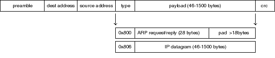 Every
Ethernet packet or frame has a header consisting of a 6-byte source address,
a 6-byte destination address, and a 2-byte protocol identifier. This is then
followed by the payload, which as mentioned before, can only have between 46
and 1,500 bytes.
Every
Ethernet packet or frame has a header consisting of a 6-byte source address,
a 6-byte destination address, and a 2-byte protocol identifier. This is then
followed by the payload, which as mentioned before, can only have between 46
and 1,500 bytes.
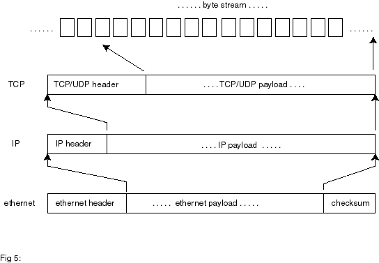
On reception of a frame without errors, this payload is ‘peeled
off’ and passed on to the rest of the system. The protocol identifier field
specifies which type of protocol is being carried by the payload. For example,
0x806 denotes an IP message.
The payload itself will have its own header and payload part,
which are dealt with by the next layer in the chain. This is the concept of
protocol ‘layers’. Fig 5
It is important to know that Ethernet data bursts or frames
are completely independent of each other. Frames are fired like bullets out
of a gun, and, apart from a collision detection mechanism during transmission,
what happens to them afterwards is of no further concern to the transmitter.
In other words, the Ethernet network layer does not provide for any global form
of flow control or error protection. At the other end, received frames are checked
for consistency by calculating their CRC. Frames arriving with errors are simply
dropped or ignored. It is up to the higher layers to provide for any form of
flow control and error protection.
It is also relevant to note that the source and destination
addresses are ‘hardware’ addresses. Known as Media Access Control (MAC) numbers,
they refer to 6-byte patterns uniquely associated with each Ethernet card and
usually assigned at manufacture. In practice the address is stored in a separate
serial EEPROM memory chip on the actual PC card. Blocks of addresses are assigned
by the IEEE to each manufacturer, so when you buy your PC card, it will have
its own unique number stored in it. You can always change this number if you
wanted to, and apart from some simple restrictions (the first byte in the sequence
must have a ‘1’ and a ‘0’ as its lower significant bits), any number can be
used as long as there are no clashes with other cards in your network.
 It
is not practical to rely on fixed hardware addresses when managing a real computer
network. Therefore, a more flexible form of addressing is used. This addressing
scheme consist of four byte sequences (known as ‘IP’ addresses). They are displayed
for human consumption as four decimal numbers, e.g. ‘192.168.0.1’.
It
is not practical to rely on fixed hardware addresses when managing a real computer
network. Therefore, a more flexible form of addressing is used. This addressing
scheme consist of four byte sequences (known as ‘IP’ addresses). They are displayed
for human consumption as four decimal numbers, e.g. ‘192.168.0.1’.
In a computer network, each workstation is allocated its own
IP address, maybe once only by the network manager, or dynamically at various
times by a program in the network server. Each workstation with an Ethernet
card will also have its own hardware MAC address.
The four byte IP address means nothing to the Ethernet card.
Ethernet frames contain only MAC addresses as destinations. Sending a packet
of data to a remote location requires knowing its MAC address.
If we connect a black box into a network containing our controller
and data logger, we must allocate it an IP address, and notify everybody else
of it. But how does the rest of the network know what our hardware MAC address
is, and how to access us? This is why we need to know about ARP.
For more on Ethernet and IP, see RFC894.
ARP
As mentioned before, the payload in an Ethernet frame can carry formats other
than IP. One such format is ARP, ARP is a simple query-response packet protocol
used to match workstations hardware addresses and IP addresses. ARP stands
for Address Resolution Protocol.
In a typical network, computers spend a small part of their
time sniffing each other, that is, sending short probe packets too see who else
is around. This is usually done on a regular, or on a ‘need to know’ basis.
The ARP protocol is used for just that. It makes use of a special MAC ‘broadcast’
destination address (0xFFFFFF). Broadcast messages are accepted by all Ethernet
stations on the network. The broadcast message basically says, "Hey out
there, anybody with IP address 190.168.0.15?" The one and only station
having this IP address allocated will then reply with a packet stating its hardware
MAC address.
In Windows, each computer builds up and maintains a local
table of IP vs MAC address pairs. Before sending a message to another station,
the table is consulted and if there is no entry, an ARP query message is sent
out. The table is dynamically maintained, flushed and refreshed every few minutes.
To see this in action, open a MS-DOS box in your computer. Now enter "C:>arp
-a". This will display the current IP/MAC address pairs for all the local
machines in your network. You may see nothing, especially if there was no recent
network activity (remember the tables are dynamic and flushed every few minutes).
Next, enter "C:>ping 192.168.0.15", (or the address of any other
station in your network), and wait to see any replies, then try "C:>arp
-a" again. Assuming our prototype controller is connected to the network,
the screen will show "192.168.0.15 4E-54-54-50-49-43" We exist!!!
Any embedded Ethernet controller must include some form of
ARP reply processing in order to respond to ‘who are you?’-type requests made
by other stations on the network. The controller also needs to include methods
for querying other workstations in the network for their MAC addresses (ARP
requests). This is one of a number of necessary overheads that push up the amount
of code required in the controller, but are essential for the proper operation
in a shared network.
More on ARP can be found in RFC 826. The next topic of interest
is IP, the ‘other’ relevant format carried by Ethernet frames. Fig I-4
IP
IP forms the backbone of all TCP and UDP messaging. IP stands for Internet
Protocol. Like the rest, each IP packet (better known as datagrams) has itself
a header and a payload component. RFC 791 is the basic document describing IP.
The most important items of information carried within the
IP header are the source and destination IP addresses. For local communications
between two stations in a local loop, the IP address in the IP header and the
MAC address in the Ethernet frame header just preceding it will correspond to
the same workstation computer. This may sound like unnecessary repetition, but
this pairing is required for routers, where the fields will be different. There
are other various fields including a checksum, a fragmentation pointer, a protocol
code for the payload, and the payload itself.
Like Ethernet frames, IP datagrams are independent of each
other and contain no in built error protection or recovery. So
why is IP necessary? IP is the common layer above all hardware dependent transport
mechanisms. Irrespectively on how the devices are electrically connected together,
fibre, radio, phone lines, all data blocks end up as compatible IP datagrams.
The job of IP is to get the data block to its destination. Its main contributions
are addressing, routing and fragmentation Remember how Ethernet frames had
a limited byte size range? Similar limitations also apply to other transport
mechanisms: optical fibre, satellite links etc. IP allows datagrams to be chopped
(fragmented) into shorter sections of the right size for transmission and vice
versa: short sections packed into single, longer datagrams.
The method employed for fragmentation is relevant for embedded
systems. Fragmented datagrams include a ‘pointer’ indexing the position of the
first byte of their data payload in an imaginary 64kb data buffer. Therefore,
each IP datagram contains exact information about the position and size of their
payload within this imaginary buffer. This allows for fragmented datagrams to
be received out of sequence. A receiver accumulates datagrams until they all
neatly fit into a contiguous block.
It follows that fragmented IP datagrams are not completely
independent of each other. This will introduce a time element in any system.
A receiver for example, has to consider when to give up waiting for missing
out of order packets, and dump any previously stored.
Fragmented datagrams cause problems with small embedded systems.
In theory, a receiver needs to allocate a 64kb buffer for every first out of
sequence datagram received. This means one buffer for every different open socket
(or channel) being serviced. This is impractical for small RAM limited systems.
One practical solution is to disallow or ignore fragmented IP datagrams. This
may not be much of a problem if the transactions involved are small, eg for
a a small data logger. However, there may be problems for systems dealing with
long streams of block-encoded data such as voice or video. Fragmentation is
not much of a problem with TCP (see later on) as TCP can be engineered to use
small segments to start with.
In a typical situation, an embedded system may need to deal
with many sources or originators. Datagrams may be arriving from more than one
source at the same time. The microcontroller will need to keep track of all,
keeping state variables for each contact, to ensure the right replies are sent
back to the right originators. In a PC this is easily handled using concurrent
threads. Small microcontrollers do not have such niceties.
Three types of IP payloads are of interest to us: ICMP, UDP
and TCP.
ICMP
ICMP stands for Internet Control Message Protocol. This is
not a protocol used to transfer messages but rather to provide a kind of internal
maintenance messaging service. One of the most common uses for ICMP is a service
known as PING. This is a method where a workstation can query another by transmitting
a special short ‘ping’ message and wait for an echo response (think of submarine
echo sounders). More on this later. Suffice to say that
any embedded implementation should incorporate facilities for echoing any PING
commands received.
ICMP replies are also commonly sent in response to failed
UDP datagrams. An embedded application should also incorporate simple facilities
for responding with ICMP ‘unobtainable’ messages. ICMP
is documented in RFC 792, 950, 1812, 1122, 1191 and 1256.
UDP
UDP stands for User Datagram Protocol. UDP is a simple Transport
Layer Protocol, it is a connectionless, unreliable protocol with no error or
flow control mechanisms. In effect, UDP is nothing more sophisticated than an
IP datagram with an extra addressing field: a port number. A port number is
an interesting concept. If a workstation has an IP number allocated to it, how
can different processes or programs in the workstation communicate at the same
time? The answer is using ports. Workstation "192.168.0.31" can use
port 21 to Telnet to another workstation, use port 80 for web access and use
port 27 for file transfers. Think of telephone extensions working off a main
private exchange number. UDP is fully described in RFC
768.
Sending a UDP message is somewhat like sending a postcard
to a friend, a simple ‘shoot and forget’-type protocol. It can be very reliable
in networks that are reliable to start with such as LANs and is normally used
for simple file transfers, remote booting of PCs or anywhere where a failure
to receive is not a disastrous issue, or one that can be simply compensated
by a repeat transmission later on. Because of this simplicity,
UDP is a simple protocol to implement in an embedded application. Simple error
recovery can be implemented at the user level, this can take the form of mindless
repetition to a simple ‘ACK’-based datagram response. Writing the software at
the PC end is also easy, as the program in Fig 2 shows.
Our controller uses UDP to demonstrate simple read and write
to a parallel and the analogue port, also for simple data connection to and
from the user serial port. UDP is an effective protocol for developing special
user applications.
TCP
TCP stands for Transmission Control Protocol. TCP is a totally
different kind of fish to UDP or to any of the protocols described previously.
TCP is a connection (point to point) oriented, reliable, byte stream service.
TCP is where all error protection and flow control is
carried out. The main document for TCP is RFC 793. With additional information
in RFC 896, 1122, 1323 and 2018.
Traditionally, error and flow control in telecommunications
was handled at the lower layers. It was recently discovered that low layer error
handling is not as effective as higher layer handling. This is one of the reasons
why the layers below TCP do no need to provide any form of error or flow management.
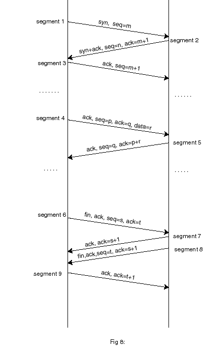 In
UDP, stations just shoot packets at each other. TCP requires the two stations
to establish a ‘connection’ first. Once the connection is established, data
can flow from one station to the other. Opening a connection is done by sending
specially flagged segments (in TCP, a packet or unit of information is called
a segment) that are used to synchronise counters and timers at either end. Fig
8
In
UDP, stations just shoot packets at each other. TCP requires the two stations
to establish a ‘connection’ first. Once the connection is established, data
can flow from one station to the other. Opening a connection is done by sending
specially flagged segments (in TCP, a packet or unit of information is called
a segment) that are used to synchronise counters and timers at either end. Fig
8
TCP requires all data to be acknowledged. Rather than acknowledging
each segment individually, TCP uses a pointer scheme where the receiver acknowledges
the position of the index or pointer of the last reliable block of data received.
Each segment thus carries a block of data plus an index pointer into an imaginary
array of bytes, that is, where the data block belongs in the array.
This scheme is very convenient as it allows segments to arrive
out of order. There is no need to acknowledge every segment received, a single
ack can be sent for more than one transmission segment received. Both transmitter
and receiver also operate a ‘data window’ scheme telling a transmitter how many
more bytes the receiver is willing to accept, this provides a form of data flow
control.
By constant adjustment of the windows and delays, TCP can
be tuned to provide an efficient flow mechanism tuned to a particular channel's
characteristics. In such a channel, the transmission line is nearly constantly
active all the time, with very few ACKs sent back. You could see efficient and
inefficient TCP in action by observing the TX and RX lights on a modem. Inefficient
TCP is when both TX and RX flash or flicker in opposition, with periods of no
activity in between. Efficient TCP is when the RX light is nearly constantly
on (denoting a nearly constant flow) with the occasional flicker of the TX ‘ACK’
light.
The standard software method uses a state transition table,
linking ‘actions’ with ‘states’ and ‘events’, plus a data control block to store
all variables for each particular connection (a.k.a. socket). In normal practice
a server (or listener) opens a new thread for every open connection request
received from a client, this thread is maintained until the connection is closed.
The state table is described in detail in RFC 793.
Implementing the full set of TCP requirements in an embedded
system is not trivial. Including each and every combination of events, states
and actions will readily inflate the program and data memory space already at
short space in a micro. In addition, threads are not easily implemented in the
smaller devices. Fortunately, some simplifications can
be made by taking a number of assumptions, for example, long-term connection
coherence and resilience to repeated and/or missing data. Depending on the use
it is put to, it is perfectly possible to implement a perfectly workable ‘lite’
version of TCP in an embedded processor.
TELNET, HTTP, FTP SMTP et al
These are higher level Application Protocols. They were designed
for specific end-to-end purposes (e.g. FTP for file transfer, SMTP for mail,
HTTP for web access) and have one thing in common. They work by sending and
receiving streams of bytes (usually ASCII characters) down an already opened
TCP connection.
In terms of implementation, these are relatively simple. One
just needs to generate the right sequence of characters (maybe even using a
BASIC-like program), as long as there is an existing TCP open channel into which
one could pipe the characters. Implementing a simple web server is nothing more
than a program that receives an ASCII serial stream, senses for special character
sequences, and sends back another sequence of characters.
RTPS
A number of alternative network models exists, most are designed
for particular applications such as stream voice, video, and real time control.
RTPS stands for Real Time Publish Subscribe, and is a good example of a recent
innovation in networking models. Nodes "publish" data onto a network
or "subscribe" to any data they need from the network. Subscriptions
eliminate the need for request traffic. The model is aimed at Real Time Control
Systems using the Ethernet, where speed of response and reaction has to be tightly
controlled. A number of companies such as General Motors have evaluated the
use of Ethernet in such schemes, and have found it a very reliable real time
transport medium.
RTPS technology is very recent, and typical of a number of
similar developments to move away from the limitations of TCP. Companies such
as RTI (www.rti.com) are offering components and toolkits under a $10k licence.
For some small Real Time applications, a subset of the technology
is all that may be necessary. I have been looking at some implementation possibilities,
and can see that this is an area that will see a lot more development in the
future.
On Telephones and modems...
I have limited the description to operation over a local area
Ethernet-based Network. This may or may not be connected to the rest of the
Internet via a router or server. Most of us will use
a dial-up Internet Service Provider. The link between us and the ISP is via
a modem, and the protocol generally used on this link is called PPP (or the
older variant SLIP). The main purpose of PPP is to encapsulate IP datagrams
into a form more suitable for modem communications; this is done by using special
escape sequences to avoid transmitting characters such as ETX which can produce
odd effects on some modem links. Extra PPP messaging
sequences are used at the beginning of the transaction to negotiate details
on the transmission methods used, types of compression, to exchange passwords
and to allocate a dynamic IP address. PPP is not implemented
in the present version of the controller. Even a simple version of PPP would
take at least 2k of program space.
Implementing PPP is not trivial. ‘Lite’ versions of the protocol
may not be very reliable, and can be very ISP dependent. PPP is a negotiated
protocol; a negotiation can sporadically fail, say by a client requesting facilities
that a server may refuse to provide at that time.
 ...And
Home Networks
...And
Home Networks
The idea of intelligent buildings and home automation has
been with us for a long time now. Many proprietary standards and protocols for
interfacing and control now exist; many are still under development. These systems
have found a slow uptake and difficult marketing, perhaps because of the high
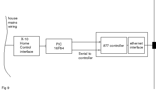
cost of the interfaces and sensors. The introduction
of low cost IP technology may influence future decisions on this subject. Fig
9 shows a way a PC LAN could be linked to an X10 Home Automation network.
There are not many common or emerging protocols for such interfaces at present.
Next Month
In the next part of this article, I shall be discussing ways of implementing
a simple controller based on a PIC 16F877 microprocessor and a standard LAN
PC card. This controller can be used for demonstrations and as the basis for
an embedded prototype interface project.
The Author
Dr Eddy Insam is a consultant in innovative applications of
telecommunications and specialises in graphics and signal processing. He can
be reached on edinsam@eix.co.uk. If you are considering
a serous application for this device, the author will endeavour to answer your
queries via e-mail.
Useful Websites:
National Semiconductors Ethernet Chip data sheet www.national.com/ds/DP/dp83905.pdf.
General X-10 Home Control Information: www.x10.com
More information on embedded Ethernet controllers:
www.embedded.com, www.chipcenter.com, www.connectone.com,
www.ipsil.com
RFC papers are available from various websites in different
formats. Try one of the search engines such as www.google.com and enter
the search word "RFC".
Useful article on Ethernet throughput and RTPS
www.sensormag.com/articles/1100/22/main.shtml
A very useful FAQ on TCP:
www.private.org.il/tcpip_rl.html
Useful References:
W.Richard Stevens. TCP/IP Illustrated, Volume 1 . Addison Wesley, 2000.
A very comprehensive guide for all aspects of TCP/IP. This
is one of the best known books in the subject.
T Lee and J. Davies. Windows 2000 TCP/IP Protocols and Services, Technical
Reference. Microsoft Press, 2000.
This book contains a CD with all published RFCs to date.
A. Jones and J Ohlund. Network Programming for Windows.
Microsoft Press, 1999.
A must for anybody involved in network and Winsock programming.
Many examples are included.
Les Hughes, Interfacing Tini. Electronics World, July
2000
A description of the Dallas Java-based web controller.
PC Interfacing Via the Ethernet
PART 2
Copyright© 2001 Eddy
Insam -email: edinsam@eix.co.uk
Abstract box
Following from last months article in which Eddy covered
the theoretical side of accessing I/O devices using the Ethernet, he now discusses
the practicalities of putting your own design together.
In last month's article, I covered some of the theory behind
designing embedded microprocessors and local networks. In this second part I
shall describe a practical implementation using a preprogrammed PIC 16F877 device,
which together with a cheap, standard LAN PC card can be used for demonstrations
and as the basis for a prototype interface project. Do
not expect too much punch from this device. After all, it is only a PIC with
386 bytes of RAM. Having said that, It can be quite an effective tool for test
and development. It is amazing what you can do with it if you have a little
bit of imagination.
Why would you want to build your own? After all, you can get
ready made $99 stamp sized devices to do a similar job. For one, if you want
to know about low level protocols, you have a special application or your product
demands a competitive edge, then you will need to be involved at a more detailed
level. The raw access provided by our device can be very useful for experimenting
with or developing special applications.
The black box approach is a quick and easy way to get results
but after all, a black box is a black box. When something doesn’t work as you
expect, the only thing you can do is look at the wall. Single sourcing and product
volatility are also just round the corner waiting to hit you hard. Not long
ago, I ordered a TCP development board from the States. By the time it arrived,
the company that made it decided to pull out of the TCP side of the business.
I am glad this device was not going to be incorporated into a manufactured product!
Having said all that, some of the ready made kits can be very
cute. One that caught my eye recently is the SitePlayer from NewMedia Inc. Maybe
because it uses a layout very similar to the project in this article or maybe
because it all fits into a single 1” by 1” printed circuit board, I shall never
know, but I liked it!
 The Circuit
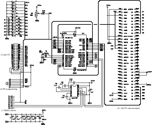
Fig 1 shows the main interface
circuit diagram. To avoid using difficult-to-obtain parts such as Ethernet line
transformers, I used a ready made cheap ISA PC LAN card; these are readily available
for less than £10 currently. The 16F877 uses quite a few of its available I/O
ports to drive the PC card: port D is used for bi-directional 8 bit data transfers,
five bits of port B are used to address the sixteen I/O mapped registers, and
the three available bits of port E are used to drive the read/write strobes.
The remaining ports are available for user interfacing, including serial communications,
reading the DIL switch, and for general purpose digital and analogue I/O.
As mentioned, only five address lines are used with the PC
card. The Ethernet chip communicates via 32 I/O mapped registers, so five bits
is all we need. The other address lines are just hardwired to map to the nominal
address range 0x300 to 0x30F, the usual default for this type of card.
You will notice that ISA PC cards have two edge connectors, and that I am using
only one here. This is because these cards were designed as plug compatible
16 bit enhancements from the original PC XT bus, which only work in 8 bit mode.
The second edge connector carries the remaining 8 data bits plus a few more
control lines. The electrical design of the card works in such a way that leaving
the second connector floating or unconnected will automatically configure the
card for XT compatible 8 bit transfers.
The only other IC device in the diagram is an RS232 converter.
This is only required if the PIC is to communicate with another controller,
PC or microprocessor via its serial interface. Of course, this is only relevant
if you want to develop your own application and drive the PIC via the serial
port. You may decide to dispense with the converter chip and provide the output
at TTL levels, after all, there is no much point in converting your data to
RS232 levels only to be converted back to TTL levels at the other end. The serial
interface operates at either 57600 bps or 2400 bps, depending on DIL settings.
I added a DIL switch to read startup conditions during reset
such as port serial speed. The PIC also operates a "cleanup" reset
to force the contents of the internal EEPROM to absolute default conditions,
this is done by forcing port C6 down while resetting the chip, hence the two
DIL positions connected to these pins.
Other DIL positions are connected in series with the LEDs
to allow the same ports to be used as inputs and avoid being loaded by the resistance
of the lights. The demonstration software mentioned later uses these ports to
flash the LEDs. No project is worth anything unless it can flash some lights
so this is a good reason for including them here. Of course, you can use these
ports for anything you like, input or output.
The various spare I/O port data lines brought out to a connector
J3. The assumption here is that there would be another PC board containing the
"user" section and other custom interfaces.
The 16F877 has an built-in 10 bit A/D converter, and can read analogue data
from any of the 5 lines in port A. This can be quite useful in our project for
reading sensors and other devices. The analogue outputs must be conditioned
to supply an output voltage range between 0 and 5 volts, as this is the range
of the A/D inputs.
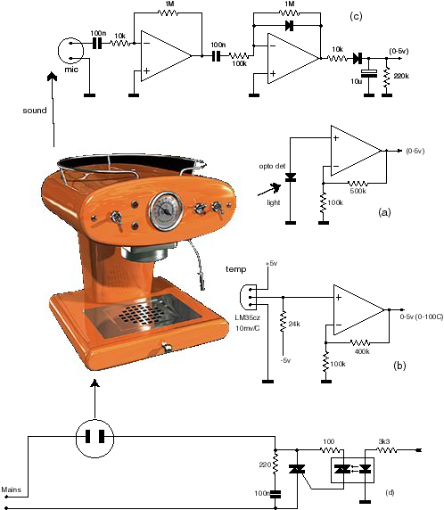 Fig
2. shows some simple examples of sensors that may
be used In a hypothetical Ethernet controlled coffee maker. In fig 2a
A standard opto detector diode is connected in voltage mode, making it respond
to the logarithm of light intensity. The two resistors provide a gain of 6-8
to bring the output to within the 0-5 volt range. Similarly, in fig 2b,
a temperature sensor, using a LM35CZ device with a sensitivity of 10mv/degree
output, is used with an op-amp with a gain of 5 to bring up the voltage output
to cover a 0-100 degree centigrade span within the required 0-5 volt range.
The LM35 is a pretty accurate device, so 1% resistors should be used if you
want to read temperatures to the nearest tenth of a degree or so. In fig
2c, the ambient noise level sensor uses a simple ceramic microphone with
a simple peak level detector to give an output roughly proportional to overall
ambient noise levels. Gain and time constants can be adjusted to suit your requirements.
Fig 2d shows how one of the outputs can be used to switch the kettle
on and off via a opto isolated triac circuit.
Fig
2. shows some simple examples of sensors that may
be used In a hypothetical Ethernet controlled coffee maker. In fig 2a
A standard opto detector diode is connected in voltage mode, making it respond
to the logarithm of light intensity. The two resistors provide a gain of 6-8
to bring the output to within the 0-5 volt range. Similarly, in fig 2b,
a temperature sensor, using a LM35CZ device with a sensitivity of 10mv/degree
output, is used with an op-amp with a gain of 5 to bring up the voltage output
to cover a 0-100 degree centigrade span within the required 0-5 volt range.
The LM35 is a pretty accurate device, so 1% resistors should be used if you
want to read temperatures to the nearest tenth of a degree or so. In fig
2c, the ambient noise level sensor uses a simple ceramic microphone with
a simple peak level detector to give an output roughly proportional to overall
ambient noise levels. Gain and time constants can be adjusted to suit your requirements.
Fig 2d shows how one of the outputs can be used to switch the kettle
on and off via a opto isolated triac circuit.
Readers who are more "digitally" inclined could
use devices such as the Dallas one-wire bus temperature probes. These sensors
do not rely on external analogue components for accuracy, and deliver their
outputs as serial bit encoded data. The outputs from these can be fed to a separate
small PIC, e.g. a 16F84, suitably programmed to generate a serial stream at
either 57600 or 2400 bps, which is then feed to the 16F877 via its serial port.
Putting it all together
You must now get a network card. Ensure the card is an ISA
card, not PCI, and uses the REALTEK 8019AS chipset. The "AS" version
of the 8019 chip includes an internal 16Kb buffer (the ‘plain’ version does
not). Many NE2000 generic cards are compatible with the 8019AS, but not all.
There may be a problem if you want to use an existing or obsolete
card from your old computer, The PnP (Plug-and-Play) system in your PC may have
initialised it to a different base address value from the default of 0x0300.
If this is the case, the micro controller may not be able to access the registers.
Try reconfiguring the card by placing it back in your PC.
Using the Windows Control Panel (in Windows 95 or 98), and reconfigure the base
address to 0x300, there is no need to change the interrupt settings as they
are not used. It may be also possible to disable PnP on the chip by hardwiring
one of the pins on the 8019AS chip to VCC, refer to the chip's data sheet to
find out the exact pin number which will depend on the device package used.
You will need a very small soldering iron.
After all the PCB has been wired up and connected together, it is time for
some tests. Plug the PC Ethernet card into the socket and power the board with
5V. The LED should start flashing at about once per second, indicating the
PIC is working and addressing the Ethernet card. Connect the unit to your PC
LAN via the BNC or twisted cable.
 Ensure DIL switches
B5-B7 are in the "off" position. This will default the chip to 57600
bps, and also enable the "demo" mode. There is no need to use the
serial port at this stage, but it could be very useful for performing initial
tests and for generally seeing what's going on. Connect the PIC serial port
interface to a spare comms port in your computer. You can use any terminal emulator
software if you have one in your PC. Alternatively, use the supplied program
"877driver.exe". This program has facilities for transmitting pre-programmed
ASCII sequences making any setting up easier. The program communicates at 57600bps,
so do ensure that bit 5 of the DIL b5 is "off", i.e. PORTB-5 or pin
38 of the PIC is not connected to ground. Fig 3.
Ensure DIL switches
B5-B7 are in the "off" position. This will default the chip to 57600
bps, and also enable the "demo" mode. There is no need to use the
serial port at this stage, but it could be very useful for performing initial
tests and for generally seeing what's going on. Connect the PIC serial port
interface to a spare comms port in your computer. You can use any terminal emulator
software if you have one in your PC. Alternatively, use the supplied program
"877driver.exe". This program has facilities for transmitting pre-programmed
ASCII sequences making any setting up easier. The program communicates at 57600bps,
so do ensure that bit 5 of the DIL b5 is "off", i.e. PORTB-5 or pin
38 of the PIC is not connected to ground. Fig 3.
With "877driver.exe" running, resetting the Controller, which will
cause the string "<Pp>" to be sent to the PC, and be shown on
the screen. This is an indication that the card is working, the character pair
"Pp" is specific to Realtek 8019 chips. You may get a different character
pair if your card uses other chipsets. If the string is not displayed at all,
the Ethernet card is not being addressed by the PIC properly, refer to the previous
note on PnP addressing.
Once you get a response, try querying the controller for its IP address. You
do this by entering the single letter Q in the transmit Edit control, or alternatively
by clicking the "Query variables" tick box, followed by a click on
the "xmit" button to send the command to the PIC.
The PIC will return a string of bytes corresponding to the current MAC and
IP allocations for the card. To display these properly, you must ensure the
screen display is set to receive in hex. Just click on the appropriate "hex
display" box.
If this is the first time you use the device, you may get the "factory
default" values. You can change these if you like using the various options
provided in the Windows software. The default IP address is "192.68.0.15".
Some people prefer to use numbers ranging from "10.0.0.1", the exact
numbers used will not matter as long as each workstation in your domain has
a different address. If your PC is part of a larger system, contact your network
manager, who will suggest a non conflicting address you can use.
You will also need to know the IP address of your PC workstation. This can
be found in Control Panel under the Network applet. If your PC is part of a
larger network, your IP address may be dynamically allocated, so it may change
from session to session. Consult your network manager, who will be able to allocate
your workstation with a fixed IP address.
The address values are retained in the PICs EEPROM for future reference, so
you will only need to enter them once. If you know your PCs allocated IP address,
enter it under "remote IP"
Open a MS DOS console on your PC and use the ping and arp commands
to check that the PC is talking to the controller and that all is working properly.
If there is no response, ensure the controller address matches the requested
ping address, also make sure the network card green LED is flashing, which shows
that packets are being fired across. The disk files supplied with the chip cover the above instructions
in more detail, including examples and lists of commands available.
 And
now for some excitement
And
now for some excitement
With "877driver.exe" running, enter the two digits "03"
in the "set status flag" box, then set the tick next to it, and click
on "xmit" to send this command to the PIC. Now watch the PC screen,
maybe nothing will happen. If this is so, get your PC to access other workstations
on the network, e.g. via Network Neighbourhood in Explorer, or start a network
printer. The screen display will suddenly start filling with packet information.
You are now watching your network connection and all packets that float past
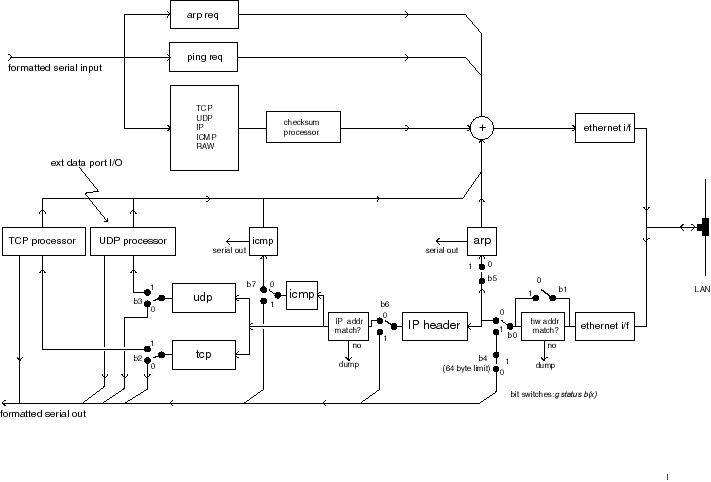
it. The command you have just entered has set the PIC to act in a "receive
all packets" mode. Fig 4 shows how the internal flow in the PIC
depends on this internal global flag.
The data will quickly fill your screen, so press the "clear screen"
button every so often. You may notice that even when all the workstations are
idle, there will be the odd packet being displayed. Soon you will easily differentiate
between ARP, ICMP, DHCP and TCP messages, and with a bit of practice (and help
from the literature) deduce where they come from and their purpose.
OK, lets do something useful, can it flash lights?
On the "set status flag" box, enter the two digits "08",
set the tick next to it, and click on "xmit". This sets the PIC to
"demo" mode. At this point, we don't need "877driver.exe"
any more, so we can close it or put it away, by minimizing it.
Now run the program "877demo.exe". This program
is a windows version of the listing shown last month. It sends a UDP packet
to the PIC via the network, retrieves a response, and then display the results.
The GUI front end lets you tick boxes to set any LEDs you want to turn on, and
will also display the returning data as digital or analogue values. The program
itself is very simple, it operates on the five least significant bits of port
C (digital output), and on return, reads port A bit 0 as an analogue voltage,
which is displayed as a voltage between 0 and 5 volts.
With "877demo.exe" running, ensure the IP addresses
shown in the top two windows correspond to that of your PC, and that of the
PIC controller. Click "send request", and wait for a response. If
nothing happens, check again that all the IP addresses are correct. Do not forget
to ensure PIC board is set to "demo" mode as described. Reset the
PIC with all the DIL switches in the off position to guarantee this.
Once you start getting a response, tick some of the LED selector
boxes and click on "send request" again. The LEDs on the PIC board
should start turning on or off according to your settings. Try adjusting the
trimpot on the PIC board, and watch how the progress bar follows it on the PC
screen every time you transmit a request.
Full C++ source code is provided to customize this program
to your needs. The software was developed in Microsoft Visual C version 6, and
it should not be too difficult to port this to other environments such as Borland
or Basic. In practice you will only need to deal with one function or subroutine,
which is fully documented to make it as easy to understand as possible. The
rest of the program is just the standard template functions used by the Visual
C environments to provide visual support for Dialog boxes, user buttons and
others.
How fast can it work?
Good you should be asking this, but a more relevant question
is "how fast can data be moved across the network?”. I have used the controller
to deliver a stream of 8 bit speech from a microphone at 8kbps, and I am sure
it could easily run faster than that. The controller itself is purely limited
by its ability to read or write the 8019 buffers via its I/O ports.
However, there are many other factors to consider as well.
In practice, the main limit is the network itself, i.e. how busy it is. There
is a major difference in performance whether you want to transmit short bursts
of high speed data, or a continuous stream of bytes at a guaranteed rate, as
the many devices on the network fight for control. Starting a network printer
or running a file transfer between two PCs would cause a noticeable flow disruption
in the latter case. It is all a bit like cars joining a busy motorway from a
side junction. So no guarantees on data transfer rates, I am afraid.
What else can you do with it?
The controller provides various levels of functionality. At
the lowest level it can deliver raw formatted Ethernet, IP or TCP packets via
its serial port. The packets are enclosed in a simple header trailer arrangement,
and simple software can be written to decode them. This is useful if you want
to build a simple network ‘sniffer’, want to develop your own protocols, or
just want to see what's going on in your network. At the highest level, it can
provide a point-to-point data stream with all necessary ARP and ICMP support
handled internally and transparently. A single flag variable controls the overall
data flow. Fig 4. On transmission you just supply
the data component of the packet, the PIC will add all checksum and size fields,
thus simplifying their generation.
A powerful combination is obtained when using the controller
with another device, e.g. another PIC. The serial port is an effective method
of communicating between the two and for passing both commands and data. In
a typical context, a separate PIC is used to accept data signals from the environment,
perform the simple conversions, and to control the 16F877 PIC controller using
plain byte and text commands. This is a very powerful option as you can develop
your own software using your own device; avoiding the complexities of network
protocols.
 The
example in Fig 9 (in last month's article) shows how an interface to
a home X10 network could be wired up. The 16F84 shown has a simple job, it only
needs to convert serial data sent from the PIC controller (at 2400bps in this
case) to X-10 type commands.
The
example in Fig 9 (in last month's article) shows how an interface to
a home X10 network could be wired up. The 16F84 shown has a simple job, it only
needs to convert serial data sent from the PIC controller (at 2400bps in this
case) to X-10 type commands.
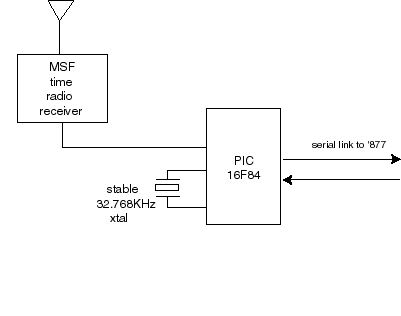
Another example of a two-chip application is shown in Fig
5. This forms the basis of a simple PC network-wide atomic clock reference.
The circuit shows a 16F84 used to decode bit data stream signals from a standard
Rugby MSF receiver. The ‘84 performs some simple conversion on the time received,
and generates a simple pre-formatted UDP data packet containing the clock information
which is reformatted as a 32 bit binary word. The exact protocol and format
is known as SNTP and is fully described in RFC 1769 and 2030. SNTP is the main
method used in Windows 2000 and other networks to align all workstations to
an external precision clock. SNTP is enabled in Windows by using the NET TIME
command. More information can be found in the http://msdn.microsoft.com technical
information website by searching under "SNTP", "Q216734"
or "Q224799"
What you can't do
The main limitation is the very small amount of RAM space
available within the PIC chip. Input data is streamed, i.e. not stored, so incoming
packets can be of any size. However output datagrams are buffered within the
chip. This buffer is dynamically allocated to whatever remaining RAM is available
at the time, usually between 80 and 200 bytes. This is enough for quite a few
applications, but not enough for everything. I tried using the internal RAM
buffer of the 8019AS for this purpose, but it appears it cannot be used in full
duplex mode, i.e. for doing DMA read and write transfers at the same time. This
buffer ceiling places a limitation on any applications that needs to deal with
large amounts of data. This means you won't be able to build sophisticated applications
such as a web server that require large amounts of data. For this, you'd be
better off buying some of the ready made cards and devices with sufficient spare
RAM or ROM.
Network Security
The Controller was originally developed as a custom tool for
validating security and throughput aspects of routers and firewalls in both
IPv4 and IPv6. Recent concerns about overloading systems using low levels SYN
attacks, incomplete IP fragments and other difficult to trace methods have made
this into a very relevant issue.
Please note that using the controller in a shared network
can cause real havoc if used irresponsibly. It can be distressing to think that
such a small device can be used to bring an apparently secure network to a grinding
halt, and without leaving any traces. So if you want to use this in a shared
office, lab or a college, please ensure you know what you are doing. Otherwise
disconnect the cable to the rest of the network.
New Standards?, do we need them?
Nowadays, print servers are using TCP and SNMP for their configuration screens.
The user just clicks open a standard internet browser to communicate with the
print driver, or with the printer itself by means of a standard web page. This
has great advantages for the printer manufacturer, he does not need to supply
special configuration software programs for the PC, it is all done via web page
commands and using a normal web browser. Of course, the Ethernet connected printer
or appliance has to act like a fully fledged web server, but as shown in this
article, this is not a difficult task, if you know how and have enough computer
power.
For point to point and time critical applications, some of
these protocols are not efficient ways of providing communications. Some concepts
such as safety, feedback paths and constant throughput have barely been considered
in the present standards which are mainly aimed at user oriented systems. So
there is a possibility that new, or variations on existing standards may be
developed specifically for certain areas of appliance and embedded device control
and communications.
Pointers? In a nutshell, IP provides for basic routing facilities,
so any new standard will reap their benefits if developed on top of this. Protocols
based on UDP are fast and easy to implement, but as UDP contains no inbuilt
error management, facilities would have to be provided by the higher layers,
which could result in degradation in performance if not done properly. TCP on
the other hand, provides a reliable flow, but it requires disproportionate overheads
both in terms of extra data and time delays. Many embedded devices may require
a reliable connection with quick response, but not necessarily a time consistent
circuit, so TCP could easily degrade efficiency. There is plenty of scope for
experimentation and coming up of new ideas.
Of course, this may not happen at all. The Hayes AT modem
command set is still in common use for computer driven applications, complete
with its idiosyncrasies and computer unfriendly command set.
And Finally..Whats Next?
I hope these articles will have made you a bit more knowledgeable
about using the Ethernet in your applications.
The main purpose was to bring the concept of network aware
devices from a "bottom up" point of view, and help to dispel some
of the "black magic" associated with ready made boxed solutions. It
should help you in seeing the wood from the trees and also open the possibility
of experimenting or developing new network techniques. Not that the world needs
any more protocols, but you may have an application where some of the existing
methods only makes you think of nuts and sledge hammers.
If there is enough interest, we shall publish more articles,
perhaps on more specific projects, and using some of the latest devices available.
Kit of Parts
A set of parts is available for this project for £35 including
VAT and p&p in mainland UK. The kit consists of a preprogrammed PIC, demo
PC software, applications notes and an instruction manual which can also be
requested from the author. More information on devices for the other applications
mentioned is also available. Please contact the author for more details
The Author
Dr Eddy Insam is a consultant in innovative applications of
telecommunications and specialises in graphics and signal processing. He can
be reached on edinsam@eix.co.uk. If you are considering
a serous application for this device, the author will endeavour to answer your
queries via e-mail.
Useful References:
It is impossible to give a thorough list of the products available,
as they are appear (and disappear) faster than we can write them down on paper.
This is just a very short selection. You may also like to try searching on the
web under the keywords “embedded and TCP”
www.Siteplayer.com
www.rabbitsemiconductor.com
www.beck-ipc.com/products/catalog/a/chip.asp?status=0_EN_products_a
www.j-works.com
www.lantronix.com/products/embedded/coboxmicro/
www.compulab.co.il
www.ibutton.com
Captions for the article:
PART A
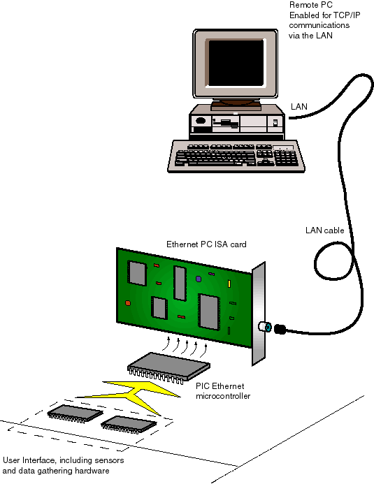
Fig I-1 (photo of a PC network card)
Caption: A cheap PC network card plus micro controller forms
the basis for a simple unit that allows a PC access to external I/O devices
via a local area network.
Fig I-2 (listing of C code, enclosed at the end of this document)
Caption: Simple C code for the PC showing how to use the Winsock
API to communicate with an external I/O device. Refer to the literature for
more examples.
Fig I-3 (block diagram, file figA3.ai)
Caption: The Ethernet chip buffers incoming serial stream and presents the
data in parallel form to the micro controller via a circular First in First
Out data buffer. The micro performs all necessary high level addressing and
decoding. Clean data is then transferred to the user application, which can
be embedded in another microprocessor.
Fig I-4 (Ethernet packet block diagram, file figA4.ai)
Caption: Ethernet frames comprise of 6-byte destination and
source addresses, plus a field word indicating the type of payload carried.
The two most common payloads relevant to the TCP/IP world are shown in the figure.
The preamble is a string of 62 bits used to synchronise the internal clock generator.
A 4-byte CRC word terminates the packet. The Ethernet interface chip strips
the headers, performs address comparison and checks for CRC validity before
placing the data block in the RAM buffer.
Fig I-5 (ip layers block diagram, file figA5.ai)
Caption: Russian dolls: each protocol packet contains inside
another packet of a higher level protocol. Each layer contributes something
to the end result: addressing, routing fragmentation, transport, error control
and error correction. The end result, in the case of TCP is a continuous, reliable
data byte stream.
Fig I-6 (DOS box showing arp command: enclosed at end of this
document)
Caption: Commands are available from the DOS prompt that allow
you to check your network interfaces. A PC workstation maintains a local cache
of other workstation addresses, which is dynamically updated every two minutes
or so. Network stations regularly transmit ARP packets to each other to maintain
their caches up to date. The DOS command arp is used to display and/or update
your local cache. These commands will only work if your machine is network enabled.
Fig I-7 (DOS box showing ping command: enclosed at end of
this document)
Caption: Ping sends a probe packet to a remote IP destination,
which just echoes the packet back. The sender can use the information collected
on the way to deduce aspects of the path, delays, users, route taken etc. The
name ping is derived from submarine echo sounders. Ping is a very useful facility
for advanced network support. The controller described in this article can be
used to generate custom ping type packets. These commands will only work if
your machine is network enabled.
Fig I-8 block diagram, file figA8,ai
Caption: Simplified diagram of a TCP conversation. Three stages are essential:
setting up the channel, the actual data transfer process, and closing down the
conversation. State transition tables are generally used in the software implement
the overall process. One set of tables and data memory buffers will be required
for every open channel. This is not practical for small microcontroller memory
limited applications.
Fig 9: block diagram in file figA9.ai
Caption: X10 Home Control Interface: a separate PIC forms
the basis of a simple interface between X10 home automation and the local area
network. No interface standards exist at present for this kind of interactivity.
PART B
Fig II-1 (circuit diagram from PCB) file fig B1.ai
Caption: The circuit diagram for the microcontroller. The
ISA socket is a standard 62-pin .1" pitch double sided edge connector as
used in most ISA PC motherboards. The trimpot and LEDs are used mainly with
the demonstration software. The circuit may draw up to 100mA from the 5volt
supply, depending on which ISA card you use.
Fig II-2 block diagram, file figB2.ai
Caption: The Ethernet capuccino maker for the person who has
everything: Various sensors for temperature, sound and light intensity can be
used to feed back data to the PC on request. Data from the PC can be used to
drive digital outputs such as the mains switch, timers etc.
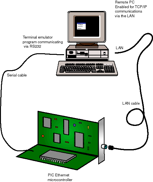
Fig II-3 block diagram, file figB3.ai
Caption: One PC can be used to test and also to drive the
controller. The PC uses two Windows programs open at the same time, one driving
the controller via the RS232 port, the other via the Ethernet network.
Fig II-4 block diagram, file figB4.ai
Caption: Internal signal flow path for the controller: The
switches correspond to bit flags in an internal register byte, and can be programmed
to modify the path of the incoming signal. This seemingly unconventional architecture
allows for various pre-processing levels for the incoming and outgoing data
blocks. An external processor handling serial character streams is then presented
with ‘pre-cooked’ data blocks, ranging from Ethernet raw packets to processed
TCP segments. The controller also adds checksum and size entries to outgoing
packets to simplify the user software. Using simple external processing power,
the device can form the basis for a network analyzer, embedded mail system or
simple web server.
Fig II-5: block diagram in file figB5.ai
Caption: X10 Home Control Interface: a separate PIC forms
the basis of a simple interface between X10 home automation and the local area
network. No interface standards exist at present for this kind of interactivity.
Fig II-6: block diagram, file figB6.ai
Caption: A practical application: A slave PIC 16F84 receives time signals from
the MSF radio receiver which are re-encoded as UDP datagrams and submitted to
the controller for sending on to the local area network. The payload conforms
to the SNTP protocol on UDP port 123. SNTP or ‘simple network time protocol’
is used in Windows 2000 networks as its main time synchronisation service, and
can be used to time lock PC workstations to an external clock reference. More
information on SNTP can be found in RFCs 1769 and RFC 2030.
FIG 2 (Note to editor: Use non proportional spaced fonts if possible)
//**************************************************************************
//** Demonstration program to show how Winsock can be used for
// communicating between a PC and an embedded ethernet device.
//
// This is a Windows console application. To run, open a MSDOS box,
// and enter the name of the program followed by optional arguments.
// Copyright (c) 2001, EIX
ltd
edinsam@eix.co.uk
//**************************************************************************
// Programming Notes:
//
// - If using MSVC, open as a Windows console application, and copy
// this file to the directory.
//
// - Program must be linked with the Winsock 2 library "WS2_32.lib".
//
// - The Winsock DLL file "WS2_32.DLL" must be present in your
system,
// usually already present in W95(SP2), W98, NT and W2K.
//
// - In order to reduce listing clutter and improve readability
// the code is kept as simple as pssible with many parameters
// hardcoded in. For the same reason, error handling is implemented
// with simple "goto" type statements.
//
// - A useful reference (with samples) for winsock programming is A Jones
&
// J. Ohlund, 1999. "Network Programming for Windows", Microsoft
Press.
//
//**************************************************************************
// Command Line options:
//
// c:> exename [ipaddress]
// where ipaddress is the destination address, e.g. 192.168.0.15
//**************************************************************************
#include <winsock2.h>
#include "stdio.h"
#include "stdlib.h"
//**************************************************************************
//** main entry point to the program
int main(int argc, char* argv[])
{
//** First, initialise any global variables to their defaults...............
char zIPadd[32];
strcpy(zIPadd,"192.168.0.15"); // default
destination IP address
//
//** Next, deal with any user input provided in Command Line ...............
for (int i=1; i<argc; i++)
{ if (argv[i][0]>='0') strcpy(zIPadd,&argv[i][0]);
}
//** Initialise Winsock 2.............................................
// Loads or increments DLL usage count. Must call WSCleanup()
on exit!
WSADATA wsadata;
if (WSAStartup(0x202, &wsadata) != 0)
{ printf ("Winsock 2 cannot be loaded, error %d",
GetLastError());
return -1;
}
//** Create our socket................................................
// Socket is initialised for UDP datagram transactions
SOCKET hSocket=socket(AF_INET, SOCK_DGRAM, 0);
if (hSocket == INVALID_SOCKET)
{ printf ("Socket creation failed, error %d", GetLastError());
goto Exit; // use simple abort to avoid listing clutter
}
//** Define destination as a socket structure...............................
// Note the use of the standard Winsock functions htons
and inet_addr
// - htons() reverses the byte endian order (as required
for IP packets)
// - inet_addr() converts IP strings such as "190.0.0.1"
into IP DWORD
SOCKADDR_IN Sdest;
Sdest.sin_family= AF_INET;
Sdest.sin_port=
htons(0x5001); //
hardcoded dest port
Sdest.sin_addr.s_addr= inet_addr(zIPadd); // dest IP
address
//** Now transmit the data..................................................
// Winsock will send the UDP datagram to the socket specified
in Sdest.
// The function also generates a local receive" port
number for replies.
//
{ // Create some useful data to transmit. We shall be hardcoding
the
// message for this demonstration.
char pTx[8];
pTx[0]=0x01; pTx[1]=rand(); // set the LEDs to some
random patter
pTx[2]=0x03; pTx[3]=0; // read the data port
in A
int
nTx=4;
// tot of 4 bytes in tx packet
// The actual TX call
SOCKET stx=sendto(hSocket, pTx, nTx, 0, (SOCKADDR*)&Sdest,
sizeof(Sdest));
if (stx== SOCKET_ERROR)
{ printf("Sendto() failed, error %d",GetLastError());
goto Exit;
}
}
//=.........................................................................
// Having sent the data packet, we now need to wait for a response. Before
calling
// the receive function, we could install a receiver timeout, this can be
useful
// for avoiding the call from blocking forever if no data is received.
{ int to=3000; // hardcode a 3 second timeout
int nr=setsockopt(hSocket,SOL_SOCKET,SO_RCVTIMEO,(char*)&to,sizeof(to));
if (nr == SOCKET_ERROR)
{ printf("setsockopt(SO_RCVTIMEO) failed, error: %d",
GetLastError());
goto Exit;
}
}
//** Waste one second.......................................................
// No need to include this in your program. This is only
here to let
// the reply packet enough time to arrive before next function
is called.
Sleep(1000);
//** Check nr of bytes in rx buffer ........................................
// Again, no need to include this function in your program.
// This is only here to show a possible way of sensing if
there are
// any bytes left in the receive buffer before calling recvfrom().
{ DWORD nb;
int e=ioctlsocket(hSocket,FIONREAD,&nb);
if(e==SOCKET_ERROR) { printf("Ioctl error:%d",GetLastError());
goto Exit;
}
printf("Rx buffer has %d characters\r\n",nb);
}
//** Call the receive function..............................................
// This function may block until the whole datagram has
been received
// (or until a defined timeout occurrs, if set as above).
{ SOCKADDR Sremot;
Sremot.sa_family= AF_INET;
int nremot=sizeof(SOCKADDR);
char pRx[256]; int nRx=256; // rx data will go here
//
SOCKET srx=recvfrom (hSocket,pRx,nRx,0,(SOCKADDR*)&Sremot,&nremot);
if (srx== SOCKET_ERROR)
{ // handle the specific "error" case of a timeout
int ee=GetLastError();
if(ee==10060) printf("Receiver timed out, no data
received");
else printf("recvfrom() failed, error %d",ee);
goto Exit;
}
// If we get this far, data was received OK, do something
wiht it!
printf("Received OK, first 4 bytes of data: ");
for (int i=0; i<4; i++) printf("%02X ",(BYTE)pRx[i]);
printf("\r\n");
}
//** Lastly, close socket, unload Winsock. and exit.........................
Exit:
closesocket(hSocket);
WSACleanup();
return 0;
}
//==========================================================================
Fig 6
(Note to editor: place in a DOS like box white letters in black background if
possible. Use non proportional spaced fonts)
C:>arp -a
Interface: 192.168.0.1 on Interface 0x2
Internet Address Physical Address Type
192.168.0.2
00-c0-df-e8-83-5c
dynamic
192.168.0.15
45-54-48-50-49-43 dynamic
C:>
Fig 7
(Note to editor: place in a DOS like box white letters in black background if
possible. Use non proportional spaced fonts)
C:>ping 192.168.0.15
Pinging 192.168.0.15 with 32 bytes of data:
Reply from 192.168.0.15: bytes=32 time<10ms TTL=128
Reply from 192.168.0.15: bytes=32 time<10ms TTL=128
Reply from 192.168.0.15: bytes=32 time<10ms TTL=128
Reply from 192.168.0.15: bytes=32 time<10ms TTL=128
Ping statistics for 192.168.0.15:
Packets: sent = 4, Received = 4, Lost = 0 (0% loss),
Approximate round trip times in milli-seconds:
Minimum =0ms, Maximum = 0ms, Average = =0ms
C:>